
An electromagnetic pulse valve is a diaphragm valve controlled by an electromagnetic or pneumatic pilot valve, which generates pulses by rapidly opening and closing a high-pressure air source. It is
primarily used in the dust cleaning systems of baghouse dust collectors. Its core components include an electromagnetic pilot head, diaphragm, valve body, and spring. The valve body is typically made
of aluminum alloy, while the diaphragm often features a nitrile rubber-cloth composite structure, providing wear resistance and high sealing performance.
The device operates by driving the diaphragm via air pressure differentials to open and close: when energized, the electromagnetic pilot head opens the venting hole to release pressure from the rear
chamber, allowing gas from the front chamber to lift the diaphragm and complete the blowing process; when de-energized, the spring resets to seal the air passage, restoring the sealed state. Based on
structure, it is categorized into right-angle type (inlet and outlet at a 90° angle), straight-through type (180°), and submerged type (inlet port located inside the air reservoir). Additionally, an ultra-low
pressure type is available for special working conditions.
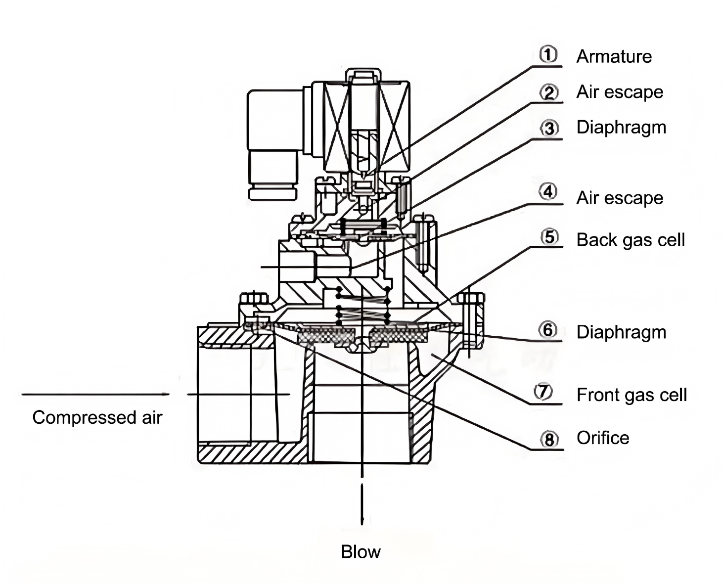
Basic Structure
The basic structure of an electromagnetic pulse valve typically includes the following components:
Electromagnetic Coil: A component that generates a magnetic field, formed by winding conductive wire into a coil.
Armature: A metal part that moves under the influence of the magnetic field generated by the electromagnetic coil.
Diaphragm: A flexible material used to isolate the front and rear air chambers and move under electromagnetic force.
Diaphragm Assembly: Includes the diaphragm and its fixing mechanism to ensure proper movement.
Front Air Chamber: Located in front of the diaphragm, connected to the fluid inlet.
Rear Air Chamber: Located behind the diaphragm, connected to the fluid outlet.
Throttle Orifice: A small hole used to regulate gas flow, controlling the inflow and outflow of gas.
Vent Hole: Used to release gas from the rear air chamber, enabling rapid movement of the diaphragm.
Rubber Sealing Ring: Ensures sealing between components, preventing gas leakage.
The working principle of the electromagnetic pulse valve can be divided into the following steps:
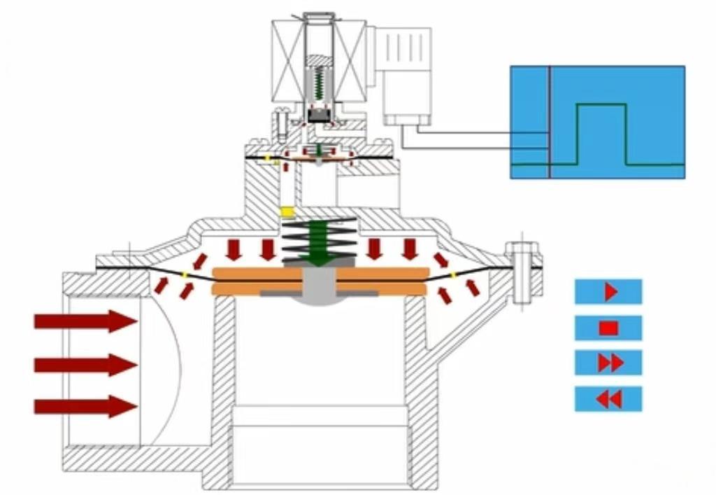
1.De-energized State
In the de-energized state, no current passes through the electromagnetic coil, and no magnetic field is generated.
The armature remains in its initial position, unaffected by a magnetic field.
The diaphragm remains in the closed position under the action of the return spring, sealing the passage between the front and rear air chambers.
The vent hole remains open, allowing gas from the rear air chamber to flow back into the atmosphere.
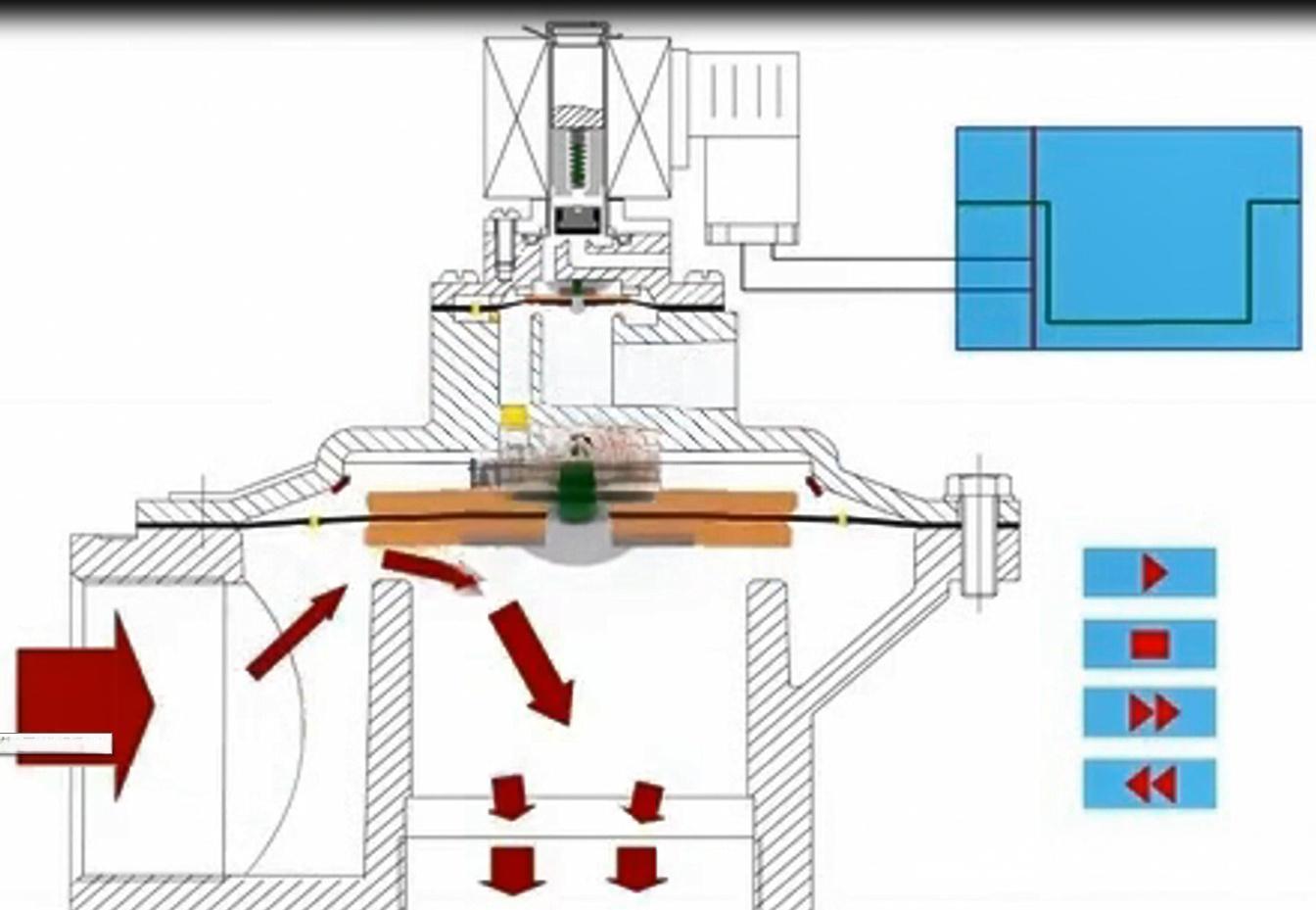
2.Energized State
When the electromagnetic coil is energized, current passes through the coil, generating a magnetic field.
The magnetic field attracts the armature, causing it to move upward.
The movement of the armature drives the diaphragm assembly, causing the diaphragm to overcome the force of the return spring and move upward.
The movement of the diaphragm opens the passage between the front and rear air chambers, allowing gas from the front air chamber to enter the rear air chamber.
The gas pressure in the rear air chamber increases, pushing the diaphragm further upward until the fluid passage is fully open.
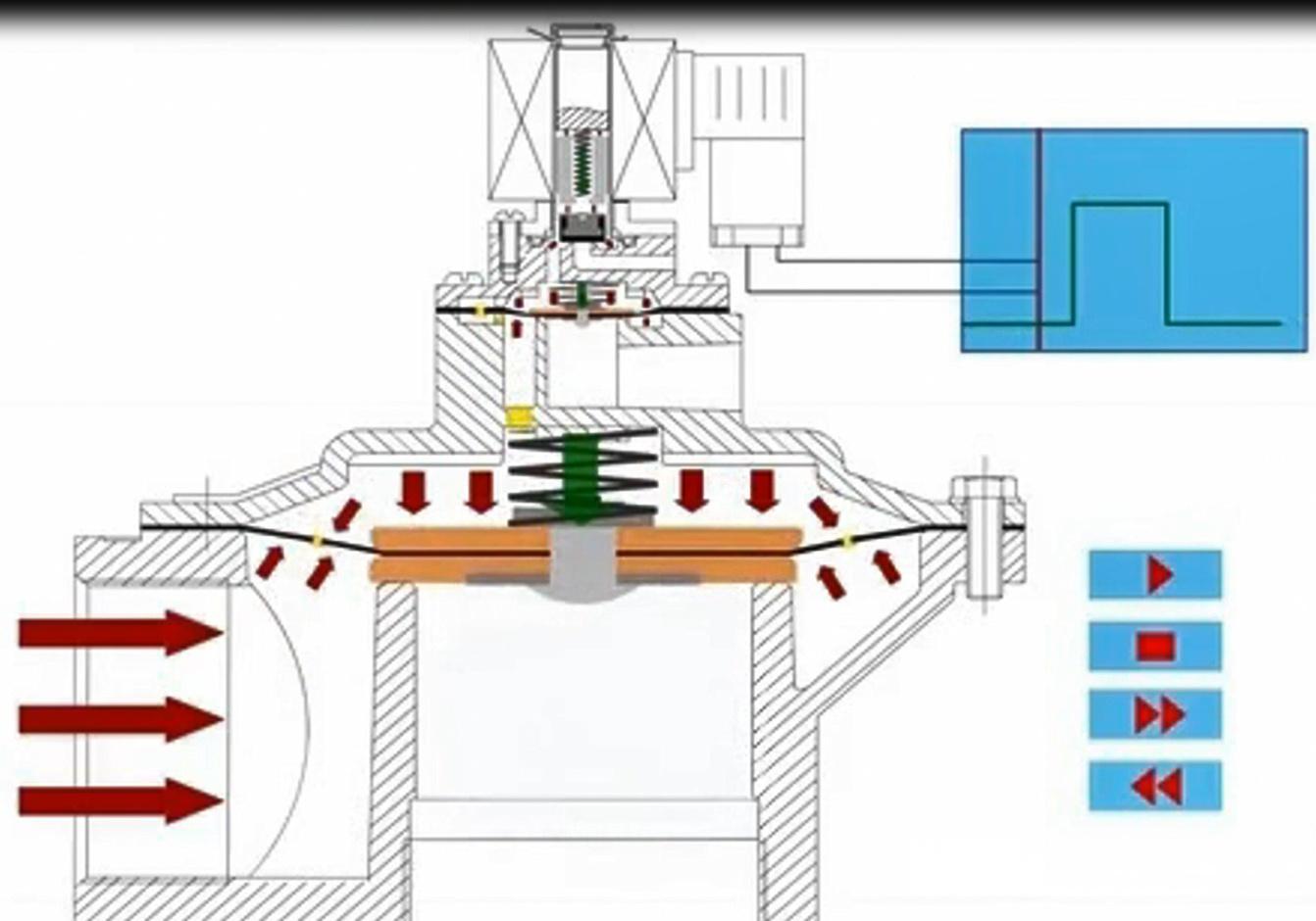
3.De-energized State
When the electromagnetic coil is de-energized, the magnetic field disappears.
The armature loses magnetic attraction and returns to its initial position under the action of the return spring.
The diaphragm assembly returns to the closed position, sealing the passage between the front and rear air chambers.
Gas in the rear air chamber is expelled through the vent hole, pressure decreases, and the diaphragm returns to the closed state.
Application Areas
Electromagnetic pulse valves are widely used in various fields, including:
Dust Removal Systems: For controlling the dust cleaning process.
Pneumatic Control: Regulating gas flow in pneumatic equipment.
Hydraulic Systems: Controlling the movement of hydraulic cylinders.
Spraying Systems: Managing the operation and stoppage of spraying equipment.
Want to know more? Contact us to get the answers you need.
Ms Yanice Yu
Qingdao Star Machine Technology Co.,Ltd.
Whatsapp/ Wechat ID: +8617852092959
Email:Yanice@starmachinechina.com
Copyright © 2025 Qingdao Star Machine Technology Co., Ltd. All Rights Reserved. Powered by HiCheng
